Goldak Technologies Inc., Dr. Loose and TIME – Institute of Technology for Metal & Engineering have demonstrated the prediction accuracy of welding structure simulation in a joint research project. For this purpose, an orthotropic plate 1200 mm x 600 mm was chosen, on which two longitudinal stiffeners and 3 transverse stiffeners were welded. The stiffeners are fixed with a total of 17 tack welds [Fig. 1]. The plate is statically constrained and supported at three corners. The fourth corner remains free. This is the corner where the greatest distortion occurs during welding. The corner opposite the free corner on the long side is chamfered so that the corners of the plate can be clearly assigned. While the stitching seams are welded, the plate on the middle transverse stiffness is supported on each outside with a stamp. Without support, the plate bends through due to its own weight to such an extent that an overly large gap between the plate and the stiffness is created.
After tack welding, the support is removed. This will cause the plate to lower at the unsupported corner. In the simulation, the removal of the support is realistically depicted.

Fig. 1: ExperimentTIME-Platte
Subsequently, the longitudinal seams are first welded on the outside, executed as a two-layer seam with 3 weld passes. All other 17 seams are designed as single-layer fillet welds. During welding, the movements to the plate are measured normally to the plate with cable wire sensors at five points. At the same points the vertical distortion from the simulation is evaluated. Figure 2, 3 and Figure 4 show the result of the validation attempt. In each of the five graphs, the vertical deformations measured with cable wires are compared with the calculated vertical deformations. On all graphs it can be seen that the deformation jump caused by the removal of the middle runs after stitching is correctly depicted at all points by the simulation. At all points, the vertical distortion is correctly calculated during the entire welding process.

Fig. 2: Result of validation TIME-Plate
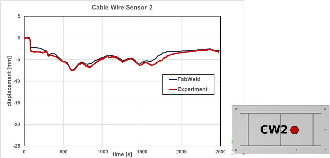
Fig. 2: Result of validation TIME-Plate Cable Wire 2
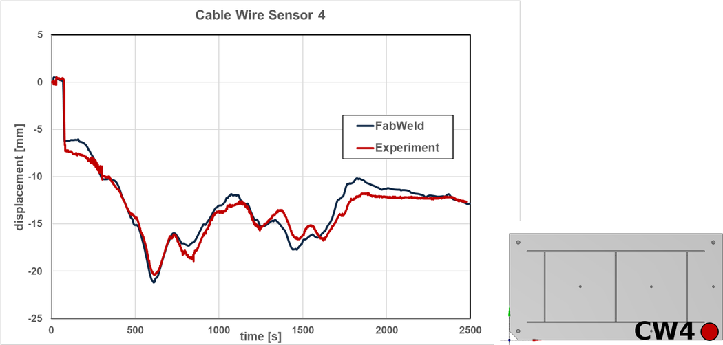
Fig. 4: Result of validation TIME-Plate - Cable Wire 4
© Dr. Loose GmbH, alle Rechte vorbehalten | Impressum | Datenschutz | Rechtliche Hinweise